Technical summary: Supercapacitors
Increased performance and declining costs will pave the way to new uses and improved system performance for supercapacitors.
Technical summary: Supercapacitors
Rapid invention and evolution in the state-of-the-art have made it difficult to stay versed in the ever-growing variety of components, devices, and technologies that could be used in the design of a product.
These developments often promise the possibility of new capabilities, improved performance, or decreased cost. To help readers stay informed, Design Concepts will be authoring a series of articles to provide a high-level overview of various technologies, what their benefits might be, and how they might be utilized. The intent is not to provide a detailed engineering discussion, but a general understanding of the topic area with enough insight to determine if it might warrant further investigation.
What is a supercapacitor?
From the micro to the nano and the mega to the giga, the development of technologies that are either diminishingly small or increasingly large are major trends. Supercapacitors, also known as ultracapacitors, fall into this category. In this review, we will explore what makes this quickly evolving type of capacitor “super,” and how its unique characteristics might be utilized.
Electrical engineers are all familiar with the capacitor as one of the fundamental elements in circuit design. It stores an electric charge with its most basic defining specification, capacitance, being the amount of charge stored per volt applied. By controlling the rate and manner by which they are charged and discharged, capacitors can be used in a variety of applications including simple timing circuits or as part of electronic filters, such as in a radio receiver, to select signals of interest.
Because they store energy when charged, capacitors are also employed in the design of power supplies. Supercapacitor development has focused on expanding the energy storage capabilities of the basic capacitor and is creating new opportunities in a variety of power related applications.
History and evolution
Development of the supercapacitor began in the early 1960s by the Standard Oil Company of Ohio as a spin-off from work being done on fuel cells. Through major changes to the internal construction, the groundwork for today’s electric double layer capacitor or EDLC (the more scientific name for a supercapacitor) was laid. The new technology increased electrode surface area tremendously and decreased the spacing between electrodes, yielding dramatic improvements in device capacitance.
Increased capacitance meant that a much greater charge was stored at a given voltage. Capacitance is measured in Farads (F) and standard capacitors in the range of 100 microfarads (.0001F) are common. In the late 1970s, Panasonic began offering the Gold Capacitor™, a new EDLC with a capacitance around 0.5F. While able to store 5,000 times more charge than its older counterpart, these early supercapacitors suffered from high internal resistance that limited how fast the charge could be extracted. For this reason, their use was limited to low power applications such as providing backup energy storage for electronic memory chips. Panasonic continues to sell a more refined version of the Gold Capacitor™ for this type of purpose today.
Over the past 30 years, companies like Maxwell Technologies have worked to extend supercapacitor capabilities not only by increasing their capacitance, but also decreasing the internal resistance. Their latest BOOSTCAP™ family exemplifies the current state-of-the-art, with capacitance as high as 3,400F and an internal resistance less than 1/10,000th of the early predecessors. The tiny internal resistance means that the capacitors can handle very large charge and discharge currents, even exceeding the capabilities of batteries.
Storage mechanism
Capacitors store energy in a manner different from batteries. In batteries, energy is stored and released electrochemically through reactions between materials within a cell. Thus, charge/discharge cycles cause physical and chemical changes within the battery and eventually cause it to wear out. EDLCs store energy as an electrostatic charge between its electrodes, no chemical reaction takes place and no changes to the internal structure occur. This allows supercapacitors to perform through millions of charge/discharge cycles.
The combination of high capacitance, small internal resistance, and high cycle life have brought supercapacitors to such challenging applications as battery load leveling within electric vehicles. When slowing or stopping, electric vehicles try to reclaim the energy removed rather than waste it as heat on the brake pads. During this regenerative breaking as well as during hard acceleration, energy is rapidly stored on or drawn from a bank of supercapacitors. Providing this reservoir to which energy can be quickly added or removed improves performance and greatly reduces the stress on the vehicle batteries.
Battery or supercapacitor?
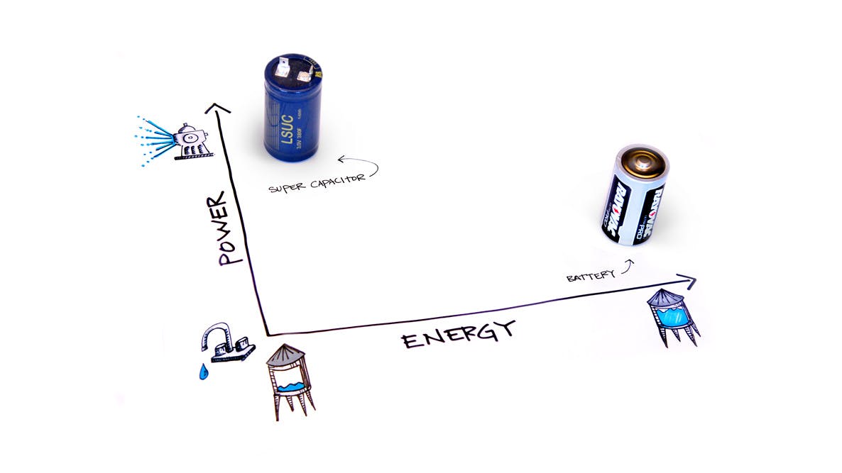
Whether to use a battery, a supercapacitor, or some combination of both is partly determined by the system’s energy density and power density needs. As the name implies, volumetric energy density is the total amount of energy stored per unit volume. The energy unit of measure is the joule (J). Power volumetric density describes the maximum instantaneous power per unit volume which can be delivered (power measured in watts, W).
By definition, one watt = one joule per second, so power is a measure of energy flow. A storage device may be able to store a large amount of energy but not be capable of delivering it very quickly; the converse is also possible. This would be analogous to a cistern where the amount of water contained represents energy stored, and the amount of flow available from the spigot relates to power.
Consider the energy and power density differences between an everyday alkaline D-cell battery (a non-rechargeable cell with good energy density) and a supercapacitor such as the 380F, 3V offering from LS Mtron Ltd. They are both packaged in very nearly the same, familiar cylindrical shape and size.
The energy stored in the battery is large, on the order of 80,000 J. The energy stored on any capacitor is equal to ½CV2. Therefore, the maximum energy stored on the example LS Mtron capacitor would be 1,710 J. The battery wins in energy density by a factor of over 46 times.
Power density is a different story. The maximum power which can be extracted from the battery, even briefly, is about 4W (and discharge at that rate would not be recommended due to internal heating concerns). This discharge rate is restricted primarily by the cell’s internal resistance. By contrast, the internal resistance of the LS Mtron supercapacitor is only 2 percent of the battery’s. Other aspects of the device construction become the limiting factor. Power surges in excess of 600W and average charge/discharge cycles of greater than 40W are possible. Applications requiring high pulsed power or power cycling are prime candidates for using supercapacitors.
Interface differences
Differences in the way energy is stored also affect how one designs a system to interface with a supercapacitor. As a battery is discharged, the voltage remains fairly constant until the battery is nearly depleted, at which point the voltage falls rapidly. The capacitor discharge profile presents more of a challenge. As noted earlier, the energy stored on a capacitor at any point in time is determined by the voltage across it. As energy is removed, the voltage deceases. Using a supercapacitor as a source of power often requires the system to operate over a broader voltage range.
Charging, on the other hand, may be simpler with the supercapacitor. So long as the maximum current and voltage limits of the device are not exceeded, virtually any current limited charging circuit/profile may be used. The only complication is to ensure the individual capacitors in a series string are charged evenly. Batteries often require a more complicated, chemistry specific profile, consisting of a constant current followed by a constant voltage charging sequence with tight control constraints.
One note about charging supercapacitors, which could take the system designer by surprise unless considered early, is the time it may take to charge them. Assume a constant current charging source is used, then the rate of change in capacitor voltage (in volts per second) is equal to the charging current divided by the capacitance. If a charging current of 10 amps (a fairly robust charging current depending on the system) were applied to the 3,400F part mentioned earlier, then the voltage rate of change would be only 0.0029 V/s and charging the capacitor to 2.85V (its rated continuous maximum) would take over 16 minutes. Of course, the long charge time when compared to what the engineer is accustomed to with traditional capacitors is due to the huge capacitance value and the resultant amount of energy stored (13,800 J in this case).
Additional advantages
Supercapacitors have a couple other advantages over batteries. They generally are specified to operate from -40 °C to +65 °C (some to +85 °C), a temperature range difficult for many batteries to achieve. Finally, inadvertent mistreatment will not result in catastrophic failures of the sort recently making headlines within certain hoverboards and cellular telephones.
Final thoughts
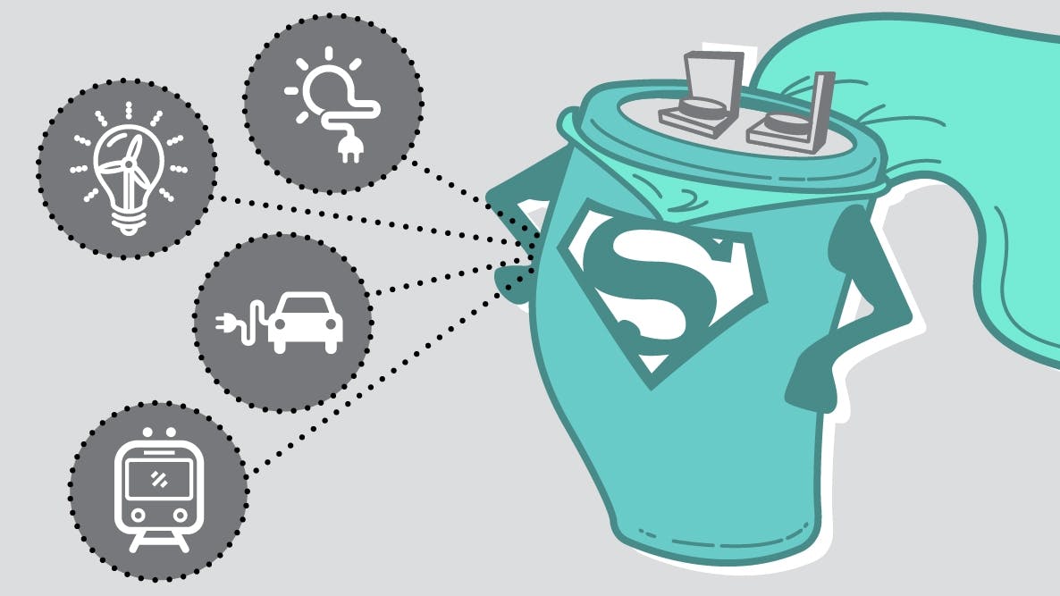
Efforts to further improve the supercapacitor technology remain a focus of ongoing industry research. The incorporation of emerging materials, such as graphene, into the electrodes and other improvements to the device construction strive to increase capacitance and voltage ratings while decreasing internal resistance. Supercapacitors are already finding application in electric automobiles, rapid transit rail, battery augmentation for diesel truck cold weather starting, and load leveling for renewable energy solar and wind power generation. Increased performance and declining costs will pave the way to new uses and improved system performance.
Written by Jeff Emmerich